Tessellation Shaders and Isolines
Written by Enoch Tsang on November 8th, 2017 for OpenGL 4.1.
I had the chance to take a graphics class at the University of Calgary, CPSC 453. In this class we learned the mathematical basis for many graphics algorithms like dithering and splines for curve interpolation. The tests were based on this material. On the other hand, the assignments for the course were quite different. They involved doing "basic" things in OpenGL. I quote basic because since OpenGL is so low level, even simple things are fairly difficult.
The second assignment involved drawing Catmull-Rom splines on top of an image. I’ve provided some background information on Catmull-Rom Splines in a different section in this article.
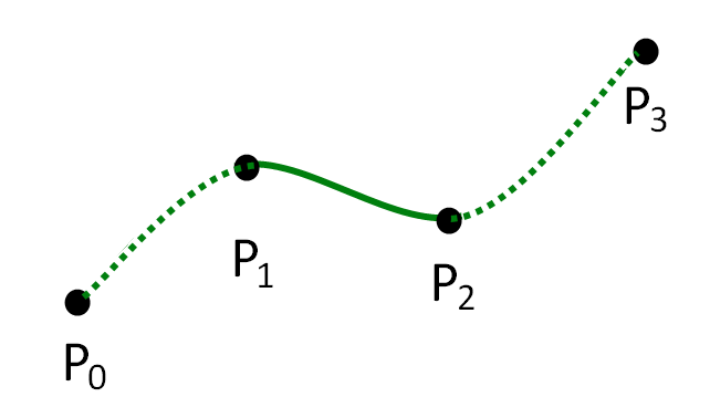
As you can see, drawing a spline involves drawing a curve. The course suggested to use tessellation shaders to draw curves (this is actually the ideal way to draw curves). But when I was looking online, guides for tessallation shaders weren’t very easy to follow. On top of that, this assignment also needed to be done with isolines (as opposed to triangles or quads), but the few guides that were online were mostly done with triangles!
In this article, I would like to provide a guide on using tessallation shaders in OpenGL with the isolines patch type. Although this article is focused mainly on isolines, I do not assume that you know anything about tessallation shaders.
Reader Assumptions
In this article, I will write on the assumption that you (the reader) have a basic knowledge of:
-
C++, just syntactically so you can follow the example code.
-
Vertex and Fragment Shaders in OpenGL. A deep knowledge isn’t necessary, just the basics of their inputs and outputs.
-
Basic algebra, to follow some of the math, some algebraic knowledge will be required.
If you don’t know OpenGL at all, I would highly recommend the learnopengl guides. In the midst of poor documentation and few beginner friendly guides online, learnopengl stood out as the go to resource.
Unfortunately, learnopengl was written for OpenGL 3.3, before tessallation was introduced to the standard, so tessellation shaders were not covered in the guides. If they were covered, I wouldn’t bother writing this article!
What is Tessallation
OpenGL mandates only two kinds of shaders for rendering, the vertex shader and the fragment shader:
-
The vertex shader’s
main()is run for every vertex and calculates per vertex attributes. This is a great place for transforming vertices to post-projection space. For example say you wanted to translate your entire vertex array a couple units up, it’s more efficient to do this in the vertex shader where the GPU parallelizes all the calculations (what it’s good at), compared to your C/C++ code where the CPU would handle it. -
The fragment shader’s
main()provides color and doesn’t do transformations per vertex.
With just these two, if we wanted to draw a curve, we would need to generate and pass every vertex in the curve in the CPU, that’s very slow!
Somewhere in between the vertex shader and the fragment shader, we need to generate more vertices than just the ones given to the vertex shader (the ones made in the C/C++ code). Tessallation shaders are great for this purpose. In a nutshell, tessallation is a step in the rendering pipeline to help us create more vertices to work with then we had in the vertex shader.
Tessellation in the Rendering Pipeline
Tessallation is right after the vertex shader in the Rendering Pipeline, and it comes in 3 parts:
-
Tessellation Control Shader (TCS)
-
Tessellation Primitive Generation (TPG)
-
Tessellation Evaluation Shader (TES)
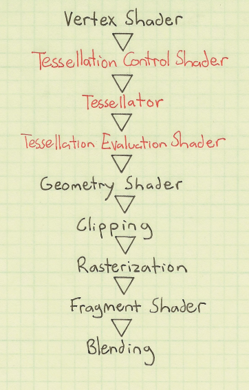
|
Note
|
Tessellation is totally optional in the rendering pipeline. To not include the tessallation stage, just don’t attach a TCS or TES to the shader program. |
The TCS and TES stages are programmable and the TPG stage is a fixed function. What I mean by programmable is that a shader is written for them. On the other hand, with a fixed function you can’t directly alter how this works, you can just affect the outputs with the input. It’s also worth noting that the TCS is also optional, it is fine to just include a TES with no TCS.
In broad terms to have a grasp at what happens in each stage we can say:
-
The TCS says how much to tessellate the vertices, and also (optionally) modifies the control (original) vertices.
-
The TPG actually does the tessellation based off what was chosen in the TCS, ultimately determining how many new vertices there will be. This stage doesn’t determine where the vertices go at all! Just how many.
-
The TES is what actually determines where every point belongs in OpenGL space (-1 to 1). It iterates through all the points created by the TPG and for each one decides where in OpenGL space it goes.
Catmull-Rom Spline Background
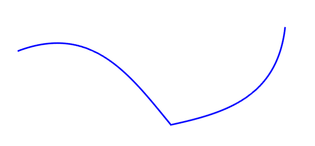
Before we continue, some knowledge on Catmull-Rom splines is required. In a nutshell, a Catmull-Rom spline is an algorithm to draw a smooth curve through many points. In math terms, that means at any point, the derivative (slope) immediately to the left and right of a point are equal.

A non-smooth curve for example would be something like below.
I won’t go into detail on how to calculate a Catmull-Rom Spline, there’s plenty of information online on that (ableit very technical and math heavy) and is not the point of this article.
But what is important to know is that to calculate a Catmull-Rom spline between two points, two more points are needed, one before the curve and one after.
In conclusion, with four points, you can draw a Catmull-Rom spline between the middle two points.
Another way of saying that is that with four points, [p0, p1, p2, p3], you can derive the equation for any point that lies between p1 and p2.
Tessellation Example
For the purpose of this article, I’ve created a GitHub repository showing a Catmull-Rom spline using tessallation shaders. All the source code is included to use and play around with.
The end result looks like this.
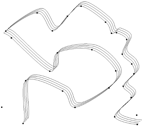
Drawing the whole spline can be split up into about 3 steps.
-
Preparing the Vertices for the tessellation control shader
-
Writing the tessellation control shader
-
Writing the tessellation evaluation shader
Preparing the Vertices for the Tessellation Control Shader
In the vertex shader, a vertex only knows about itself and can’t calculate any new information based on other vertices (it technically can with uniforms but that’s not what it’s supposed to do). In comparison to tessellation shaders, they can calculate information based on other vertices, but not all of them, only the same vertices within the same patch.
Patches are an important concept in tessellation shaders. Before passing the vertices to a tessellation shader, the vertices must be split into patches and then the TCS must be told how many vertices are in each patch. Telling the TCS how many vertices are in a patch is done with the function call:
glPatchParameteri(GL_PATCH_VERTICES, 3);In this case, we tell the rendering pipeline that there are 3 vertices per patch, we refer to this as the patch size.
This should be called right before the the draw command you use, like glDrawElements() or glDrawArrays().
You can see an example of its usage in the src/CatmullRomSpline.cpp file in the GitHub example.
|
Note
|
There are a max number of vertices you can put per patch. You can get it using glGetIntegerv(GL_MAX_PATCH_VERTICES, &maxPatchVertices);. This number is most commonly 32. |
Putting this together, if the vertex shader received the points u, v, w, x, y, z, and our specified patch size was 3.
The Tessellation control shader would receive the 2 patches [u, v, w] and [x, y, z].
Let’s take a look at a Catmull-Rom spline now. Consider the following points and curves.
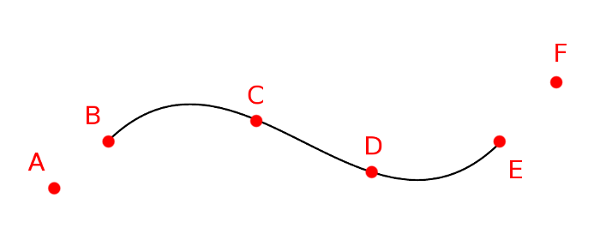
At the end of tessellation we want to have interpolated all the vertices to draw the curves, using the control points a to f.
If we wanted to draw the first curve (between b and c, we would need the first four points a, b, c, and d.
The next curve would then be between points c and d, requiring points b, c, d, and e, and so on.
This translates into what needs to be in each patch. The patches that we would need to pass into the TCS would be:
[a, b, c, d]
[b, c, d, e]
[c, d, e, f]
Where each letter is one vertex and each set of [] is one patch.
To do this, we pass the vertices sequentially into the vertex shader, so like a, b, c, d, b, c, d, e, c, d, e, f.
Then we split them up into patches using GL_PATCH_VERTICES.
|
Note
|
Passing the vertices sequentially in this fashion can be done a number of ways. I used an element buffer object along with a vertex buffer object in the full example on GitHub. |
Writing the Tessellation Control Shader
Now we have our information in the patch format that we need. Using this, the TCS needs to output the following information:
-
Outer tessellation levels in
gl_TessLevelOuter[4]. -
Inner tessellation levels in
gl_TessLevelInner[2]. -
The output "control" vertices in
gl_out.
Tessellation Levels
In brief, tessellation levels define how much to tessellate an object.
In other words this means how much to split it up, or how many new vertices to create.
There are 6 different tessellation level values that can be provided to the TPG, four outer tessallation levels and 2 inner tessallation levels.
Different patch types use the tessallation levels differently, this particular guide is aimed towards the isolines patch type (more about patch types in the next section).
With isolines, the only tessellation levels considered by the TPG are gl_TessLevelOuter[0] and gl_TessLevelOuter[1].
The last two outer tessallation levels and inner tessallation levels are unused by the isolines patch type.
-
gl_TessLevelOuter[0]specifies how many isolines to create, this becomes the maximum value forgl_TessCoord.yin the TES. -
gl_TessLevelOuter[1]specifies how many times to split up a particular line, this how far apartgl_TessCoord.xis in different invocations.
It’s not quite correct to say what this looks like, because only the evaluation shader actually decides where the vertices go in space, but here is an example to conceptualize what the two tessallation levels do.

Take a moment to guess what the values of gl_TessLevelOuter[0] and gl_TessLevelOuter[1] are.
…
The correct answer is 3 for gl_TessLevelOuter[0] and 4 for gl_TessLevelOuter[1].
In this case for drawing a Catmull-Rom spline, gl_TessLevelOuter[1] will determine how smooth the curve will look.
gl_TessLevelOuter[0] doesn’t really have too much effect on the end result, but I’ve used it in the example code to draw multiple lines for effect.
Output Vertices
The TCS receives a set number of vertices for a number of patches. The number of patches that the TCS outputs must be the same as the amount that it receives. But what can differ, is the number of vertices per patch.
The number of vertices per patch given to the TCS is defined in GL_PATCH_VERTICES.
The TCS defines how many vertices per patch to output.
This is defined in the TCS file with:
layout(vertices = n) out;In actual code, you wouldn’t write n but pick an actual numerical value.
A patch is represented in the built-in provided variable gl_out, the format is as follows:
out gl_PerVertex
{
  vec4 gl_Position;
  float gl_PointSize;
  float gl_ClipDistance[];
} gl_out[];
Notice that gl_out is an array, the size of the gl_out array is the same as the number in
layout(vertices = 2) out;In the case above, the size of gl_out would be two, meaning the output patch size is 2.
Great so that means, there is complete freedom to define the vertices that go to the TPG and TES!
Actually… not quite.
There’s a gotcha, you can only write to the vertex that the current invocation is for. Let’s talk about how often the TCS is invoked.
Invocations
layout(vertices = 2) out; not only defines the number of output vertices per patch, it also partially defines how many times the TCS main() is invoked.
For every output vertex for every patch, the TCS is invoked once.
Let’s slow down for a second and talk about what it means for a shader to be "invoked".
One invocation means one call to a shader’s main() function.
In a GPU, at each stage, everything is parallelized by default.
By comparison, in normal code, running something multiple times usually means running it in a loop, so each call is sequential.
So in a GPU, this means when we write our shader, it’s important to understand that every invocation to a shader is happening at the same time.
Hopefully saying "one invocation" makes a little more sense now.
Going back to how many times the TCS is invoked, you can figure out which output vertex the current invocation is for in main() with the built in variable gl_InvocationID.
The current patch that is being operated on can also be determined using gl_PrimitiveID.
The OpenGL standard has mandated that only the gl_out index that is the same as the gl_InvocationID can be written to.
You can still read from the other indices at any time though.
What this means, is that the following code is dangerous.
gl_out[0].gl_Position = gl_in[1].gl_Position;
It’s dangerous because gl_out is being written to for an index that isn’t absolutely the same as gl_InvocationID.
In fact, the above shader code won’t even compile on some platforms.
The correct way to write to the 0th index would be below.
if(gl_InvocationID == 0) {
        gl_out[gl_InvocationID].gl_Position = gl_in[1].gl_Position;
}
This ensures that we are on the 0th invocation when gl_out[0] is being written.
TCS Example Explanation
Here is the tessellation control shader from the example.
#version 410

layout(vertices = 2) out;

patch out vec4 p_1;
patch out vec4 p2;

void main()
{
        if(gl_InvocationID == 0) {
                gl_TessLevelOuter[0] = float(4);
                gl_TessLevelOuter[1] = float(64);

                p_1 = gl_in[0].gl_Position;
                p2 = gl_in[3].gl_Position;
        }

        if(gl_InvocationID == 0) {
                gl_out[gl_InvocationID].gl_Position = gl_in[1].gl_Position;
        }

        if(gl_InvocationID == 1) {
                gl_out[gl_InvocationID].gl_Position = gl_in[2].gl_Position;
        }
}
Let’s walk through this line by line.
This defines the OpenGL version this shader is meant for, 4.1.0.
#version 410
The curve is only drawn between two points, so our output patch should only have 2 vertices.
layout(vertices = 2) out;
If you’re familiar with uniforms, this is similar.
This allows patch specific information to be passed from the TCS to the TES.
In this case, a vec4 called p_1 and p2 will be made available for the same patch in the TES.
patch out vec4 p_1;
patch out vec4 p2;
The main() function gets invoked for every output vertex in every patch.
void main()
The stuff happening in this if block only needs to happen once per patch, so we do it just once when gl_InvocationId == 0.
That last number could’ve been 1 and wouldn’t have made a difference.
But a warning, that if different invocations for the same patch write different values to the variables in this if block, bad things will happen.
if(gl_InvocationID == 0) {
Here we say the number of isolines is 4 and to split up each line into 64 segments.
                gl_TessLevelOuter[0] = float(4);
                gl_TessLevelOuter[1] = float(64);
A Catmull-Rom Spline still needs four points to be calculated even if they’re not the control points.
So we pass in the first and last point through patch variables.
p_1 is supposed to mean p negative one.
They’re named p_1 and p2 because the two middle points will be p0 and p1 in the TES.
So in the TES there will be points p_1, p0, p1, and p2.
                p_1 = gl_in[0].gl_Position;
                p2 = gl_in[3].gl_Position;
The goal here is to set the first vertex of the out patch to be the second vertex of the in patch.
It makes a lot of sense to write gl_out[0].gl_Position = gl_in[1].gl_Position, but because a gl_out index can only be written to on the same invocation id, this if statement is necessary.
        if(gl_InvocationID == 0) {
                gl_out[gl_InvocationID].gl_Position = gl_in[1].gl_Position;
        }
This is similar to the last section, it sets the second vertex of the out patch to be the third vertex of the in patch.
        if(gl_InvocationID == 1) {
                gl_out[gl_InvocationID].gl_Position = gl_in[2].gl_Position;
        }
Writing the Tessellation Evaluation Shader
Now at this stage, the TCS has told the TPG how much to tessellate each patch. The TPG has done its calculations and gives tons of vertices to the TES. It’s now the TES’s job to determine the position for each of the vertices.
Invocations
For the TES, I’ll start with when main() in the TES gets invoked.
The TES’s main() will be invoked for every interpolated vertex generated by the TPG.
Remember the tessellation levels defined in the TCS?
That tells us how many vertices got generated by the TPG and therefore tells us how many vertices the TES operates on.
The amount of vertices also varies depending on the patch type.
layout (isolines) in;This defines the patch type, in this case it is isolines.
The other options include triangles and quads, but this article will only focus on isolines.
So let’s recap what we got here:
-
The number of isolines created is 4, from
gl_TessLevelOuter[0] = float(4);. -
The number of segments for a line is 64 from
gl_TessLevelOuter[1] = float(64);. -
Only those two tessellation levels matter because the patch type is
isolines.
So this means for each patch, the TES is invoked 4 * 64 times, 256 times, 256 vertices per patch!
Each of these vertices need to be told their own location in the OpenGL space (-1 to 1). Where is that defined?
Outputs
Defining the position for each vertex is actually the same as in the vertex shader, with the output gl_Position.
The difference is, the vertex doesn’t have its OpenGL position passed to it already like it probably was in the vertex shader.
It needs to be calculated from some other input values.
Inputs
The built in values that we can work with are gl_TessCoord and gl_in.
For isolines, gl_TessCoord has two valid values, x and y:
-
gl_TessCoord.xtells us how far along the line the vertex is. -
gl_TessCoord.ytells us which isoline the vertex is on.
gl_in is per patch information that we get from the TCS.
It’s the same as the gl_out variable that was defined in the TCS, meaning it’s an array of the control points.
For this Catmull-Rom Spline example, it will be an array of two.
Slope Example
Before we dive into calculating values along a curve, let’s do something simpler and easier to grasp.
Interpolating a straight line between p0 and p1.
#version 410 core

layout (isolines) in;

void main()
{
        vec4 p0 = gl_in[0].gl_Position;
        vec4 p1 = gl_in[1].gl_Position;
        float u = gl_TessCoord.x;

        float slope = (p1.y - p0.y) / (p1.x - p0.x);
        float x = ((p1.x - p0.x) * u) + p0.x;
        float y = (u * slope * (p1.x - p0.x)) + p0.y;
        gl_Position = vec4(x, y, 0.0f, 1.f);
}
Let’s take a closer look through this.
This section helps us use the data given from the TCS.
Remember that the TCS gave the second and third point of our original patch data.
So gl_in[0] here is actually the second point from our original patch data.
        vec4 p0 = gl_in[0].gl_Position;
        vec4 p1 = gl_in[1].gl_Position;
Here gl_TessCoord.x tells us how far along in the line we are.
In many curve equations, it is the t value.
For vertices very close to the first control point, i.e. gl_in[0], the value will be close to 0.
For vertices very close to the last control point, in our case gl_in[1], the value will be close to 1.
float u = gl_TessCoord.x;
So now we have some math work to figure out the actual gl_Position from this information.
This line calculates the slope between p0 and p1, a simple rise / run formula, we’ll use this later.
float slope = (p1.y - p0.y) / (p1.x - p0.x);
This calculates the x coordinate in OpenGL space.
-
First we get the
x(horizontal) length of the line we’re on usingp1.x - p0.x. -
Then we multiply that by how far along we are on the line,
(p1.x - p0.x) * u. -
Now we have how far we should be from the first point
p0.xin OpenGL space. -
We then add the
p0.xvalue to find exactly where this point goes in OpenGL space.
float x = ((p1.x - p0.x) * u) + p0.x;
This calculate the y coordinate in OpenGL space.
-
First we calculate the
yvalue in respect tou, this is the smaller space where points close top0are 0 and points close top1are 1. We do this just by multiplying the slope byu, like the common line equationy = mx. -
Next we convert that to world space similar to how we did for
u.u * slope * (p1.x-p0.x). -
Lastly, similar to calculating
x, again we addp0.yto find exactly where the point goes in OpenGL space.
float y = (u * slope * (p1.x - p0.x)) + p0.y;
Putting all that together, we now have the x, y coordinate in OpenGL space for this vertex.
We put that in gl_Position and the vertex is done.
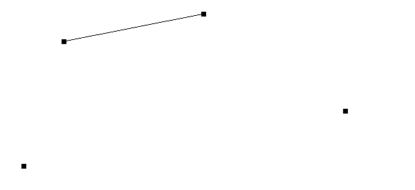
I’m sure you noticed that gl_TessCoord.y was unused, by not using this we just say every isoline gets drawn the same way.
All the lines will be together and just look like one line.
The end result for four points looks like this.
Curves
The slope example can now be done with a curve. I won’t go over the details of how to calculate a Catmull-Rom Spline. But basically, we replace the slope equation, with the equation for a Catmull-Rom Spline.
        float slope = (p1.y - p0.y) / (p1.x - p0.x);
        float x = ((p1.x - p0.x) * u) + p0.x;
        float y = (u * slope * (p1.x - p0.x)) + p0.y;
Gets replaced with:
        float b0 = (-1.f * u) + (2.f * u * u) + (-1.f * u * u * u);
        float b1 = (2.f) + (-5.f * u * u) + (3.f * u * u * u);
        float b2 = (u) + (4.f * u * u) + (-3.f * u * u * u);
        float b3 = (-1.f * u * u) + (u * u * u);
        vec4 new_pos = 0.5f * (b0*p_1 + b1*p0 + b2*p1 + b3*p2);
And voila, the points for a curve are calculated.
Using the gl_TessCoord.y Value
You probably noticed, that so far the gl_TessCoord.y value hasn’t been used yet.
This value, again, determines which isoline we’re on.
We can use this value to slightly move each line so that they are in different locations.
        float v = gl_TessCoord.y;
        gl_Position = vec4(new_pos.x + v * 0.08, new_pos.y + v * 0.08, new_pos.z, new_pos.w);
So here we shift the calculated x and y, right and up respectively, based on the gl_TessCoord.y value.
So for the first isoline, v == 1, the line will be translated rght and up by 0.08.
The second isoline, v == 2, will be translated right and up by 0.16 and so on.
So each isoline gets placed in a slightly different location.
The result of this is what you see in the final result.

Ignored Topics
Because this topic was only focused on isolines, the other tessellations levels were not discussed. Those were not the only ignored relevant parameters. I don’t plan to cover them all in this article because it is already quite long, but I will at the very least acknowledge the topics that I have ignored:
-
Tessellation levels
-
gl_TessLevelOuter[2] -
gl_TessLevelOuter[3] -
gl_TessLevelInner[0] -
gl_TessLevelInner[1]
-
-
Patch types
trianglesandquads -
Per vertex attributes
-
gl_PointSize -
gl_ClipDistance[]
-
-
TES Spacing like
fractional_even_spacingorfractional_odd_spacing -
Primitive ordering (not relevant at all for isolines)
-
User-defined per vertex variables
-
OpenGL patch parameters
GL_PATCH_DEFAULT_OUTER_LEVELandGL_PATCH_DEFAULT_INNER_LEVEL
Information on all these topics are all online. For further reading I would recommend https://www.khronos.org/opengl/wiki/Tessellation.
